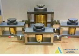
Dielectric Constant (Dk), also known as Permittivity, is a fundamental property of a material that represents the ability of the material to conduct electromagnetic waves. It primarily affects aspects such as transmission speed and delay in electronic signal or radio wave transmission. In terms of capacitance, it influences the magnitude of the capacitance value.
Dissipation Factor (Df), also known as Loss Tangent, is another fundamental property of a material. It measures the energy loss of electromagnetic waves passing through a material. Higher dissipation factors result in more energy consumption, leading to a decrease in signal strength.
The most common method for measuring Dielectric Constant and Dissipation Factor involves using a Resonant Cavity. The basic principle of a resonant cavity is the presence of an electromagnetic wave within the cavity. This electromagnetic signal is typically generated using an antenna. By measuring the frequency shift and Quality Factor (Q Factor) before and after inserting the sample into the cavity, one can calculate the Dielectric Constant (Dk) and Dissipation Factor (Df) of the sample。
- SPDR
Arcanum Advanced Inc. provides resonant cavities at different frequencies suitable for measuring thin samples such as PCB materials, ceramics, PTFE, PET, Polyimide, Teflon, and more. Different types of materials may require different testing conditions and resonant cavities. For specific details, please contact our sales.
The SPDR method is for the test frequency from 1GHz ~ 10GHz, and also the SPDR method can only test one frequency point with each cavity. Frequency: 1, 3, 5, 7, 10 GHz
SPDR:
Follow IPC-TM-650 2.5.5.15, It’s a methodology with constant frequency (1, 3, 5, 7 GHz) The thickness from 100um~1mm depends on the frequency chosen. The test sample size should be 100 mm x 100 mm. The SPDR methodology is the most popular way that CCL companies measure the material they make.
• Operating Frequency - 1 GHz ~ 10 GHz
• Sample Thickness Requirement - 0.5 ~ 2 mm
• Sample Size Requirement - 140 x 140 mm
- SCR
The SCR Method could test frequency range from 10GHz ~ 84 GHz. Depending on the ability of the MUT it might seem 5 frequency points in one Cavity.
Follow IPC-TM-650 2.5.5.13, This methodology can have multi-test frequencies in one cavity (test frequency & point depend on test samples). The thickness should be from 10um~500um depending on the sample characterization. The sample size should be 80mm x 80mm. The SCR test methodology is used to test the frequency over 10 GHz, 84GHz is the highest frequency it can test.
•Operating Frequency - 10 GHz ~ 40 GHz
• Sample Thickness Requirement - < 0.5 mm
Sample Size Requirement - > 150 x 150 mm
- Capacitance
Follow IPC-TM-650 2.5.5.9, the method could test the frequency from 1Hz to 1GHz. The method can test 10um to 1mm thickness. This method is different from others, because of the test frequency, we’ll use the LCR meters to be the main frame to to test.
• Operating Frequency - 10 kHz ~ 7 MHz
•Sample Thickness Requirement - > 2 mm
•Sample Size Requirement - 150 x 150 mm
- Microstrip
Follow IPC-TM-650 2.5.5.5
This method can be tested with sweep frequency from 8GHz to 12 GHz.
The thickness should be 100um~1mm.
This method is a way to help us test some samples that need the Z-axis test way, like fiberglass.
- BCDR
Follow IEC 63185
This methodology could test the frequency from 10GHz to 110GHz in one cavity.
The thickness needs to be 10um~500um depending on the test frequency you need.
This methodology is a way to help us check some products like radar or satellites.

Feedback list